
 Stainless HPLC Fittings
 Inline Filters
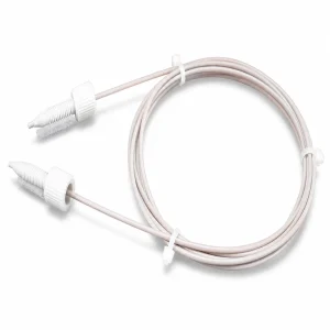 PEEK Sample Loops
 Plugs & Ferrules
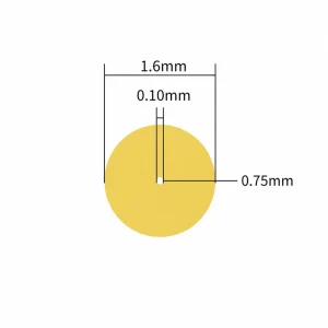 PEEK Tubing
 PTFE Tubing
 Silicone Pump Tubing
 Stainless Capillary
 GL45 Solvent Caps
 Waste Systems
 Laboratory Reservoirs
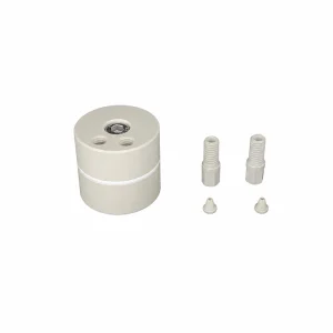 Bubble Traps
Flownectra / Engineering Guide
A practical way to choose fittings, tubing, filtration and flow-control components when the result depends on a clean, stable and serviceable line.

Choose the right starting point in 30 seconds
Use this matrix to identify the first component to specify. It is a decision aid, not a substitute for the model-level drawing and compatibility information on each product page.
| Your first constraint | Start with | Why it comes first | Verify next |
|---|---|---|---|
| Analytical or HPLC path | Tube ID/OD and compression interface | The connection and internal volume can change the result before material choice becomes the limiting factor. | Fitting standard, ferrule pairing, bore, solvent and pressure. |
| Very limited sample or reagent | Internal volume of the complete path | A long or oversized line consumes sample during priming and delays the next composition change. | Tube length, ID, loop volume, fittings and flush plan. |
| Repeated compression in a pump head | Pump-tube bore and wall | The tube must recover predictably and sit correctly in the pump track. | Pump-head geometry, routing, wear and replacement interval. |
| Frequent operator disconnects | Connection mechanism | A service connection should be easy to identify, clean and reconnect without rebuilding the line. | Luer or quick-disconnect geometry, pressure, fluid and orientation. |
| Particles or gas are expected | Filter, frit or bubble-trap location | Protection works only when the component is placed where it can capture the problem and be serviced. | Pore size, flow direction, restriction, venting and access. |
| Bottle or waste container is part of the route | Cap ports and vent path | A poor cap layout can create leaks, contamination or an accidental closed container. | GL45 or S60 interface, port count, tubing OD and safe waste routing. |
What a laboratory fluid path actually contains
Think of the path as a chain rather than a single hose: source, pickup tube, pump, valve, filter, process chamber or detector, and waste. Each segment has a job. Each boundary between segments has an interface. The design is complete only when the chain is continuous in three ways:
- Hydraulically continuous. The bore does not suddenly collapse, widen into an unnecessary cavity or become blocked by a mismatched connector.
- Chemically continuous. Every wetted surface is suitable for the fluid, concentration, temperature and exposure time.
- Operationally continuous. Operators can prime, drain, inspect and replace service parts without confusing clean, sample and waste paths.
This model explains why a component can be perfectly usable in one position and unsuitable in another. A filter that protects an inlet may be a restriction if installed after a pump. A quick disconnect that is convenient on a service panel may add too much internal volume for a short analytical loop. The right question is always: what does this part do at this exact point in the path?
How tube size changes volume, flow and delay
Tube ID is not just a catalog dimension. It sets the cylindrical volume of the line and strongly affects the resistance to flow. For a straight round tube, the ideal geometric volume is:
V = pi x (ID / 2)2 x LUse one unit system throughout. If ID and L are in millimeters, the result is in cubic millimeters; 1,000 mm3 equals 1 mL. Fitting cavities and bends add to the installed volume.
As a worked example, consider a 2.0 mm ID tube with a 1,000 mm length. The ideal cylindrical volume is approximately 3,140 mm3, or 3.14 mL. That number is a geometry example based on the stated dimensions; it is not a flow rating and does not include connectors.
Volume becomes a timing issue when a line must be flushed or when one solution replaces another. A simple estimate is:
time = installed volume / flow rateAt an assumed 1 mL/min, 3.14 mL would take about 3.14 minutes to pass through an idealized line. Real systems take longer or show dispersion because of mixing, compliance, restrictions and the way the instrument detects the change.
Pressure drop also depends strongly on bore. Under laminar flow of a Newtonian liquid in a straight round tube, the Hagen-Poiseuille relationship shows that pressure drop is proportional to viscosity, length and flow, and inversely proportional to the fourth power of ID. In that limited model, halving the ID increases the pressure drop by a factor of 16 if all other variables stay constant. Actual instruments include fittings, valves, non-Newtonian fluids and transitional flow, so use the relationship to understand direction and sensitivity, not to claim a system rating.
Connection standards: how the seal is made
Two fittings can look similar while sealing in completely different ways. Identify the sealing surface before deciding how tight is tight enough.
| Connection type | Sealing principle | Good fit for | Common mistake |
|---|---|---|---|
| Compression fitting and ferrule | A ferrule grips the tube and seals against the fitting body. | HPLC capillary tubing and fixed analytical assemblies. | Wrong tube OD, incomplete insertion or repeated reuse of a deformed ferrule. |
| Tapered Luer | The mating tapers create the seal; threads, when present, provide retention. | Sampling, low-pressure service connections and accessories where the taper is correct. | Treating every Luer as pressure-equivalent or forcing a non-Luer taper together. |
| Thread with gasket or O-ring | The gasket or elastomer closes the fluid path while the thread supplies clamp load. | Bottle caps, bulkheads and serviceable enclosures. | Assuming the thread itself is the seal, or ignoring panel thickness and gasket seating. |
| Quick disconnect | Matching halves engage; many designs include an internal valve or shutoff. | Maintenance points and lines that must be disconnected repeatedly. | Leaving particles on the mating faces or reversing flow direction after service. |
Thread tape is not a universal leak cure. If a fitting seals at a ferrule, taper, gasket or O-ring, tape can interfere with seating and introduce fragments. Follow the fitting maker’s installation method and use thread sealant only where the design calls for it.
Material choice is more than a compatibility chart
A chemical compatibility table answers one question: whether a material is likely to resist a fluid under stated conditions. A reliable path asks several more questions.
- Temperature cycling. Repeated heating and cooling can change stiffness, seal compression and the way a tube sits in a fitting.
- Mechanical duty. A rigid capillary, a flexing service line and a tube compressed thousands of times in a pump head need different mechanical behavior.
- Surface interaction. Adsorption, extractables, particles and gas permeability may matter even when the bulk material is chemically resistant.
- Cleanability. A reusable analytical line may justify a different material and geometry from a disposable sampling line.
- Traceability. Record the actual material and model so a replacement does not silently change the process.
PEEK, PTFE, FEP, PP, PPS, silicone and 316L can all be useful in laboratory systems. None is automatically correct. Verify the supplier’s data for the exact grade, fluid, temperature, pressure and exposure time before release.
Filtration and bubble control: place them deliberately

Particles and gas behave differently, so they need different design responses. A frit or filter captures particles; a bubble trap gives gas a deliberate place to separate. Installing either one without checking its restriction can simply move the problem to a new location.
- Place a particle barrier upstream of a narrow passage when protecting that passage is the priority.
- Place a bubble-trap volume where gas can collect and be removed without sending it into the detector, valve or pump head.
- Mark the intended flow direction and keep the component accessible for inspection and replacement.
- Confirm pore size, wetted material, pressure capability and expected flow with the component data sheet.
- After service, prime slowly and inspect the first waste stream rather than assuming a clear line is particle-free.
Four path layouts to use as a design exercise
These are not fixed recipes. They are useful sketches for deciding which constraints and measurements to collect before selecting a part.
| Layout | Example chain | Design questions |
|---|---|---|
| HPLC solvent or sample | GL45 cap port > PEEK or fluoropolymer tube > compression fitting > instrument port | Does the tube OD match the ferrule? Is the line short enough for the method? How will it be flushed? |
| Peristaltic dosing | Reservoir > flexible pickup > silicone pump tube > quick disconnect > process inlet | Does the bore and wall suit the pump head? Where is the wear section? Can the operator replace it without disturbing the clean side? |
| Microfluidic branch | Source > frit or filter > PEEK capillary > check valve > bubble trap > chamber | Where will particles stop? Where will gas collect? Which element contributes the largest internal volume? |
| Waste and vent | Instrument outlet > waste tubing > S60 cap > contained bottle, with a defined vent path | Is the waste container protected from spills and back pressure? Are clean, sample and waste connections visually distinct? |
For bottle interfaces, see the GL45 HPLC solvent caps and S60 waste-bottle components. The point is not to copy a layout blindly; it is to make the complete route visible before you order individual pieces.
Why fluid paths fail at the interfaces
Most laboratory lines do not fail because a length of tubing suddenly stops being tubing. They fail where one part meets another: a ferrule that was never fully seated, a tube that was cut at an angle, a thread that is almost, but not actually, the same standard, or a material that was chosen without checking the solvent.
Those small mismatches have measurable consequences. In chromatography, an unnecessary pocket can add dead volume and broaden a peak. In a dosing line, a tiny bubble can make the delivered volume look unstable. In a peristaltic pump, the wrong wall and bore combination can change how the tube recovers after compression. A good design makes these failure modes difficult to introduce and easy to diagnose.
Choose the path by the job
Begin with the operation, not the catalog category. The same instrument may contain several very different paths, each with its own priorities.
| Path or operation | What matters most | Typical Flownectra building blocks |
|---|---|---|
| HPLC solvent or sample line | Low extra volume, clean cuts, secure compression connections and chemical compatibility | HPLC fittings, PEEK or 316L capillary tubing, sample loops |
| Microfluidic or analytical branch | Small internal volume, predictable bore, bubble control and repeatable service connections | PEEK tubing, check valves, bubble traps and filter components |
| Peristaltic pumping | Elastic recovery, correct wall thickness, clean routing and a replaceable wear section | Silicone pump tubing and compatible connectors |
| Bottle-to-instrument transfer | Closed routing, secure cap ports, venting where required and protection from dust | GL45 solvent caps, PEEK ports and tubing |
| Waste, vent and bubble management | Safe containment, low restriction, particle capture and visible gas removal | S60 waste caps, activated-carbon components, frits and bubble traps |
| Panel or service connection | Positive orientation, quick maintenance and a connection that cannot be confused during reassembly | Luer fittings, quick-disconnect couplers and panel-mount accessories |
1. Specify the interface before the material
A tube can be chemically perfect and still be the wrong part if its interface does not match the instrument. Record these details before ordering:
- Tube ID and OD. ID influences restriction and internal volume; OD determines which ferrule, sleeve or clamp can grip it.
- Connection standard. Confirm the thread or taper instead of relying on a visual match. A metric thread, an imperial thread and a Luer taper are not interchangeable.
- Orientation. Note male/female ends, straight or angled geometry, and whether the fitting must rotate after the tube is installed.
- Panel thickness and access. Bulkhead and bottle-cap parts need enough thread engagement and room for a wrench or hand tightening.
- Service intent. A permanently assembled analytical line has different priorities from a line that operators disconnect every day.
For compression fittings, push the tube fully to the fitting shoulder before tightening. The ferrule should grip the tube without crushing the bore. For polymer tubing, use a sharp cutter and keep the end square; a slanted or deformed cut can create a pocket that traps liquid or gas.
2. Match the material to the fluid and the motion
Material names are useful shorthand, not a compatibility decision. Check the actual solvent or sample, concentration, temperature, pressure and exposure time against the specific material data for the part.
| Material family | Where it is often useful | Questions to verify |
|---|---|---|
| PEEK | Rigid, low-volume analytical tubing, HPLC fittings and sample-path components | Is the bore correct? Is the fluid and temperature within the supplier’s compatibility guidance? |
| PTFE, FEP and other fluoropolymers | Chemically demanding laboratory transfer lines and flexible capillary runs | Will the tubing stay supported and kink-free? Does the connection grip the selected OD? |
| PP and PPS components | General laboratory couplings, bottle accessories and serviceable assemblies | Is the part exposed to a solvent or temperature outside its intended range? |
| Silicone | Peristaltic pump wear sections and flexible, replaceable lines | Will repeated compression, adsorption or swelling affect the process? |
| 316L stainless steel | Rigid capillary runs and assemblies that need a metal tube and clean compression interface | Is the internal surface and fluid chemistry suitable for the application? |
The table is a starting point, not a release specification. Always use the relevant supplier compatibility chart and your process conditions for final selection.
3. Treat dead volume as a design variable
Dead volume is the part of a path that is not effectively swept by the main flow. It can be a fitting cavity, an overlong tube end, an adapter stack or a badly cut tube. In an analytical path, it can smear the timing of a change in composition. In a dosing path, it can delay or dilute the next dose.
- Use the shortest practical run and the smallest bore that meets the required flow and pressure drop.
- Remove adapters that do not solve a real interface problem. Every extra transition is another place for a pocket or leak.
- Seat tubing all the way to the stop. A few millimeters of missing insertion can become a surprisingly large volume in a small-bore line.
- Cut polymer tubing with a dedicated sharp tool. Inspect the end under magnification when the path is analytical or microfluidic.
- Flush and prime after assembly. Capture the first waste stream when particle carryover matters.
Flownectra components for a considered build
The following groups are organized by the problem they solve. Product pages contain the model-level dimensions and options; use those details to complete your interface specification.
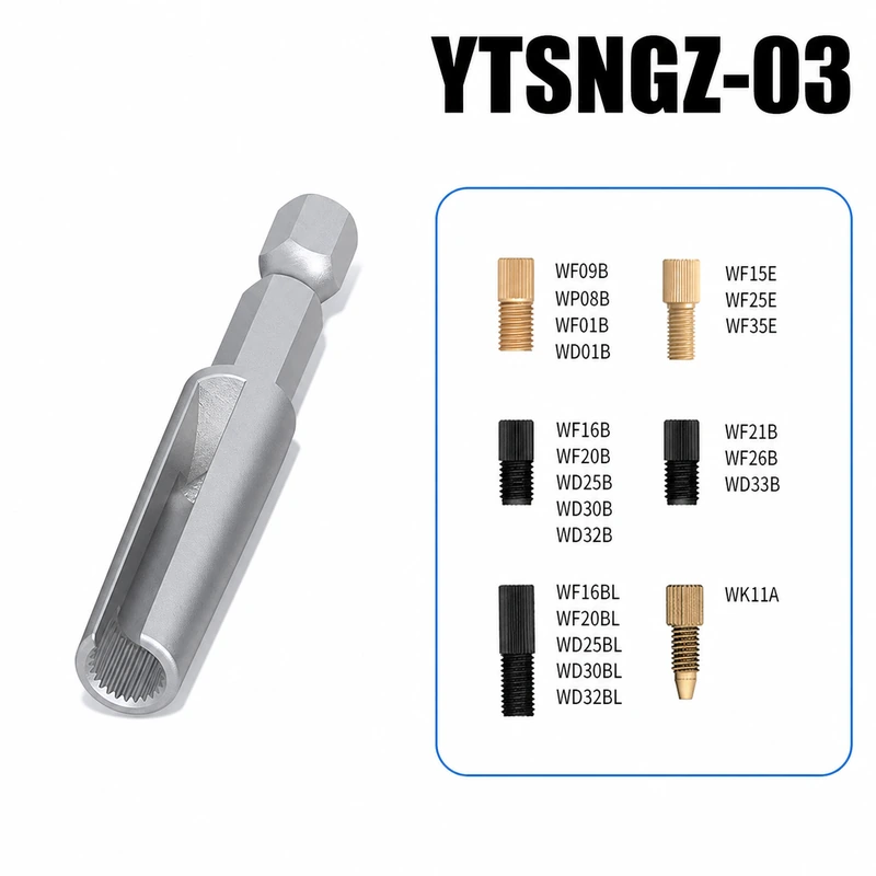
HPLC fittings, ferrules and plugs
Compression fittings establish the mechanical seal between a capillary and an instrument port. Pair the fitting and ferrule with the tube OD, and keep the tube end square and fully seated.

PEEK capillary tubing
PEEK is a practical choice for rigid, low-volume analytical runs when the bore, OD and chemical limits match the method. Avoid forcing a tube into a fitting with the wrong grip size.

PTFE and FEP tubing
Fluoropolymer tubing can simplify chemically demanding transfer paths. Route it with gentle bends, support long runs and confirm that the selected connector is intended for its OD.

Silicone pump tubing
The pump tube is a wear component, not just a hose. Match the bore and wall to the pump head, keep the tube centered in the track and replace it when recovery or output changes.

Luer and quick-disconnect couplings
Luer fittings are useful for serviceable low-pressure connections and sampling accessories. Quick-disconnect couplers help operators break a line without rebuilding the entire path.

Filters, frits and bubble control
Frits and filters protect narrow passages from particles; bubble traps give gas a deliberate place to collect instead of letting it travel into a detector or pump.
Close the bottle and waste path
A solvent bottle or waste container is part of the fluid path. A cap with the right ports keeps tubing organized and can make venting, filtration and replacement repeatable. For solvent handling, see the GL45 HPLC solvent caps. For waste routing, see the S60 waste-bottle components.
A practical build sequence
-
Map the path. Draw the source, pump, valve, detector or process chamber, and waste. Mark every interface and the direction of flow.
-
Write the constraints. Record fluid chemistry, expected temperature and pressure, target flow, allowable internal volume and how often the line will be serviced.
-
Lock the tube size. Choose ID for flow and volume, then choose OD so every fitting, ferrule, clamp and bulkhead shares the same grip dimension.
-
Select the fewest interfaces. Use direct fittings where possible. Add a Luer, quick disconnect, filter or bubble trap only when it provides a clear operational benefit.
-
Assemble cleanly. Cut square, remove dust, seat each tube to its stop and tighten according to the fitting maker’s instructions. Do not use thread tape on a fitting that seals at the ferrule or taper.
-
Prime and test. Flush with a compatible liquid, inspect every joint, check for bubbles and monitor pressure or flow stability before connecting a valuable sample.
-
Document the service parts. Record tube material, dimensions, connector model and installation date. Make the pump tube and filter easy to identify and replace.
Troubleshooting: read the symptom as a location clue
| Symptom | First checks |
|---|---|
| Leak at a compression joint | Confirm tube OD and ferrule pairing; check that the tube reaches the stop; inspect for a scratched tube end or overtightened/deformed ferrule. |
| Pressure rises or fluctuates | Look for a kink, crushed bore, blocked frit, particulate contamination or a fitting standard that is restricting the passage. |
| Broad or delayed analytical response | Audit internal volume: long loops, adapter stacks, poor tube insertion and cavities around non-matching interfaces. |
| Bubbles reach the instrument | Check solvent preparation, loose suction joints, cap venting and whether a bubble trap is placed where gas can actually separate. |
| Carryover or unexplained contamination | Flush the new line, inspect frits and filters, replace suspect tubing and separate clean and waste paths during service. |
| Pump output drifts | Inspect tube centering, compression, wear and recovery. Verify that the tube’s bore and wall match the pump head. |
FAQ
Can I mix PEEK, PTFE and stainless-steel parts?
Often, yes, but the connection still has to be mechanically correct and chemically suitable. Mixing materials is not a substitute for checking the fluid, temperature, pressure and sealing method at each joint.
Is a Luer connection suitable for every laboratory line?
No. Luer fittings are convenient for service and sampling, but the pressure, fluid and required dead volume determine whether they belong in a particular path. Use the fitting where its geometry and rating fit the job.
How do I reduce bubbles after changing tubing?
Make clean cuts, tighten the source-side joints, prime slowly with a compatible liquid and inspect the bottle cap and suction path. If gas is expected, provide a defined bubble-trap location instead of relying on an arbitrary high point in the tubing.
What information should I send when asking for a component recommendation?
Send the fluid or solvent, tube ID and OD, connection standard, pressure, temperature, target flow, available panel or port dimensions and whether the line is analytical, disposable or frequently serviced. That information is more useful than a product photo alone.
Further reading
- IDEX HPLC Fittings Guide – how fitting choice, tubing dimensions and dead volume affect HPLC connections.
- GL Sciences: Tubing connection in HPLC – tube insertion, square cuts and common causes of extra volume or pressure.
- Thermo Fisher HPLC fittings and tubing resources – connection and tubing selection references.
- Cole-Parmer chemical compatibility resources – a starting point for checking tubing and component materials against chemicals.
Browse Flownectra’s HPLC fittings, laboratory tubing, pump tubing and custom fluid components. For a specification-based recommendation, send the interface and process details listed above.
